Build a physical prototype
I wired the Arduino and components on a breadboard to explore the traffic-light sequence and countdown behavior. The photograph and short demo are my own prototype record.
Entry 03 / Embedded hardware
A breadboard first. A PCB design next.
Breadboard built · PCB v1 designed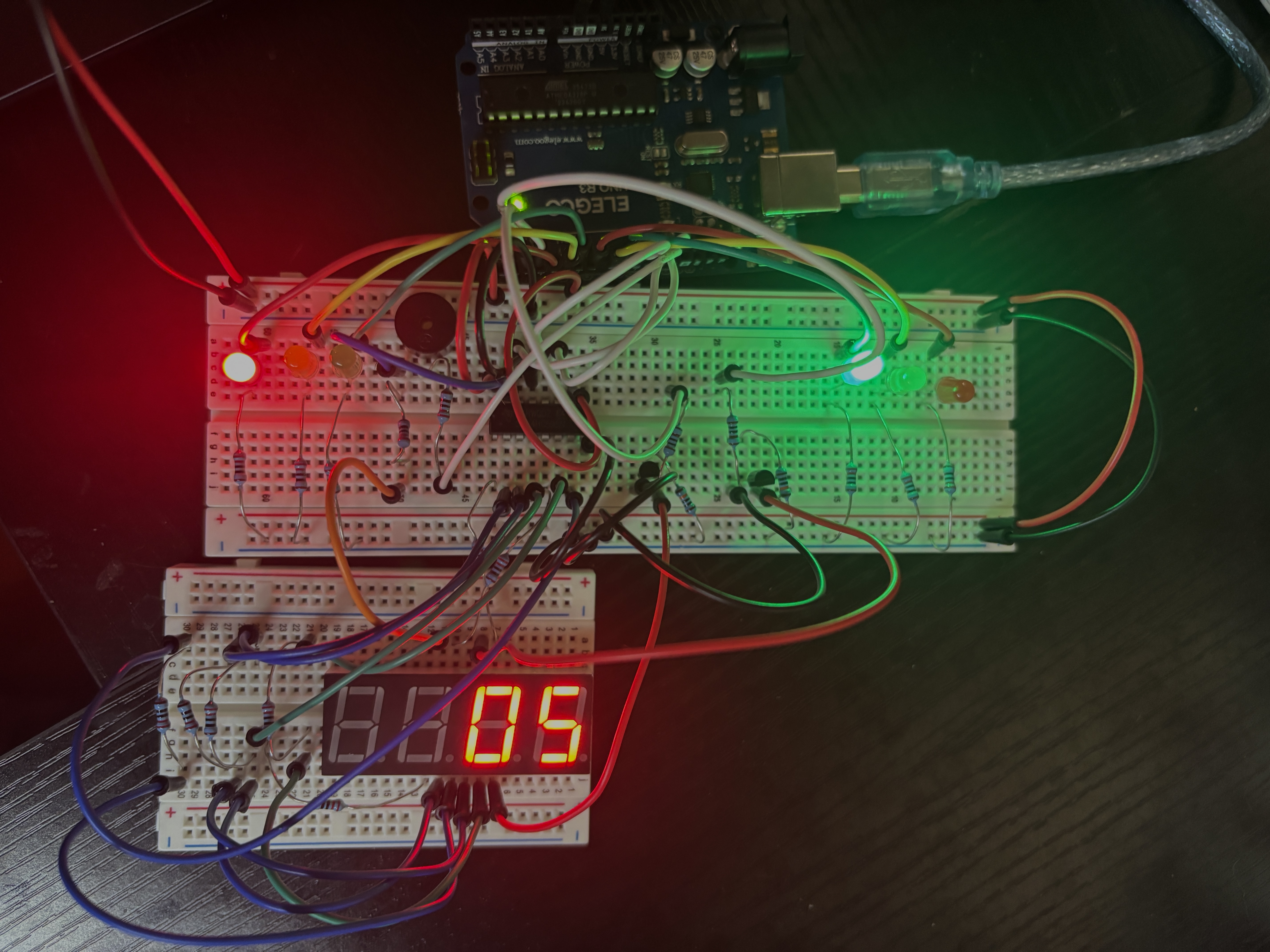 MY BREADBOARD BUILD
01 / The work
I built the breadboard prototype shown below, then worked on a PCB version in KiCad. This was an early project that gave me hands-on practice connecting a controller, display, and discrete components. The prototype and the PCB are separate stages: the breadboard was built, while the PCB remains a design.
I wired the Arduino and components on a breadboard to explore the traffic-light sequence and countdown behavior. The photograph and short demo are my own prototype record.
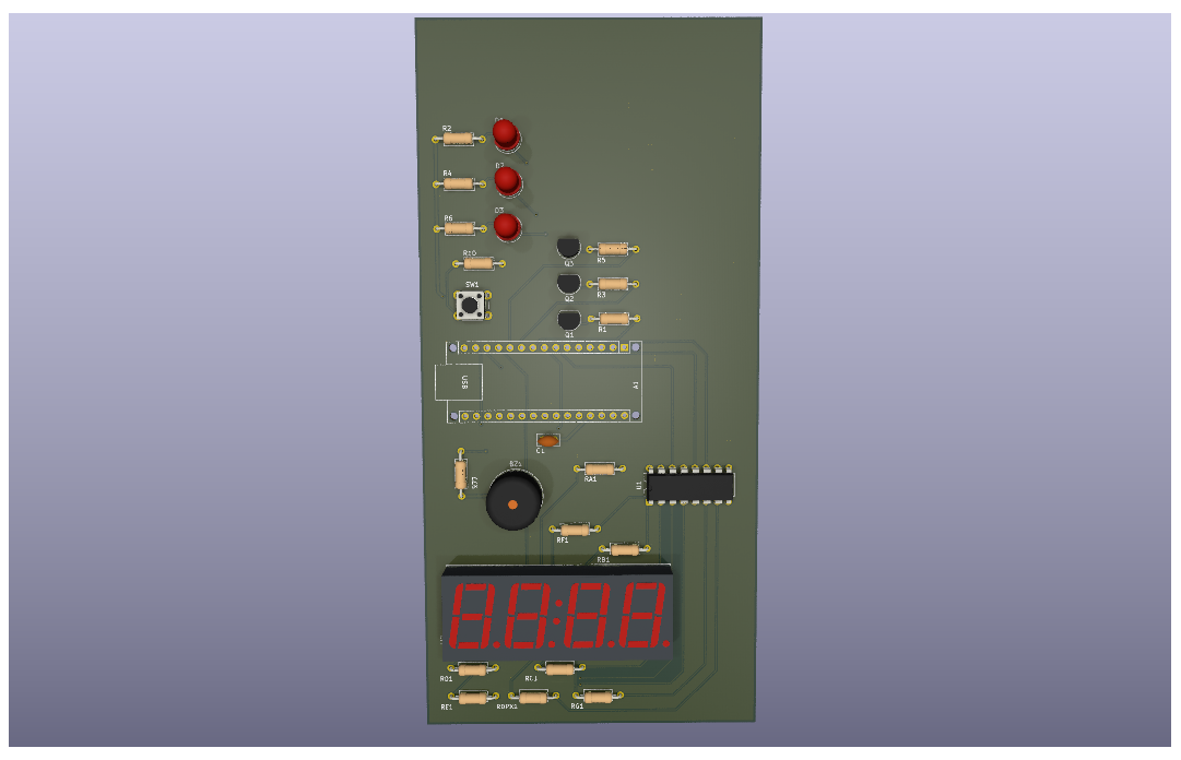
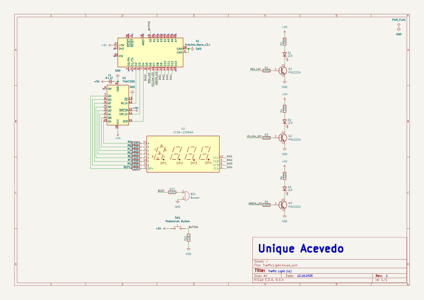
The board design uses an Arduino Nano, a 74HC595 shift register, a four-digit seven-segment display, transistor-driven traffic LEDs, a buzzer, and a pedestrian button. The schematic and board files are available to inspect directly.
I kept the BOM, Gerbers, board renders, footprint files, and original project notes together. The firmware is not in the current repository snapshot. Before building the PCB, I need to verify the display part and footprint pinout and run a complete design review.
02 / Visual record
Open a photo or drawing to inspect the details, or play an available prototype demo.
The physical Arduino prototype I built; the later PCB uses a Nano.
A short video record of the breadboard prototype.
The recording shows an Arduino connected to breadboard circuitry, a numeric display, and traffic-light LEDs. It documents the breadboard prototype; the PCB shown in other images was not fabricated.
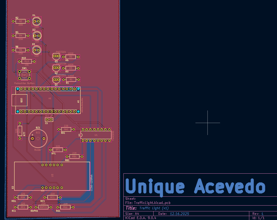
Vector preview exported from the KiCad source.
Version 1 of the board layout.
KiCad render, with component positions visible.
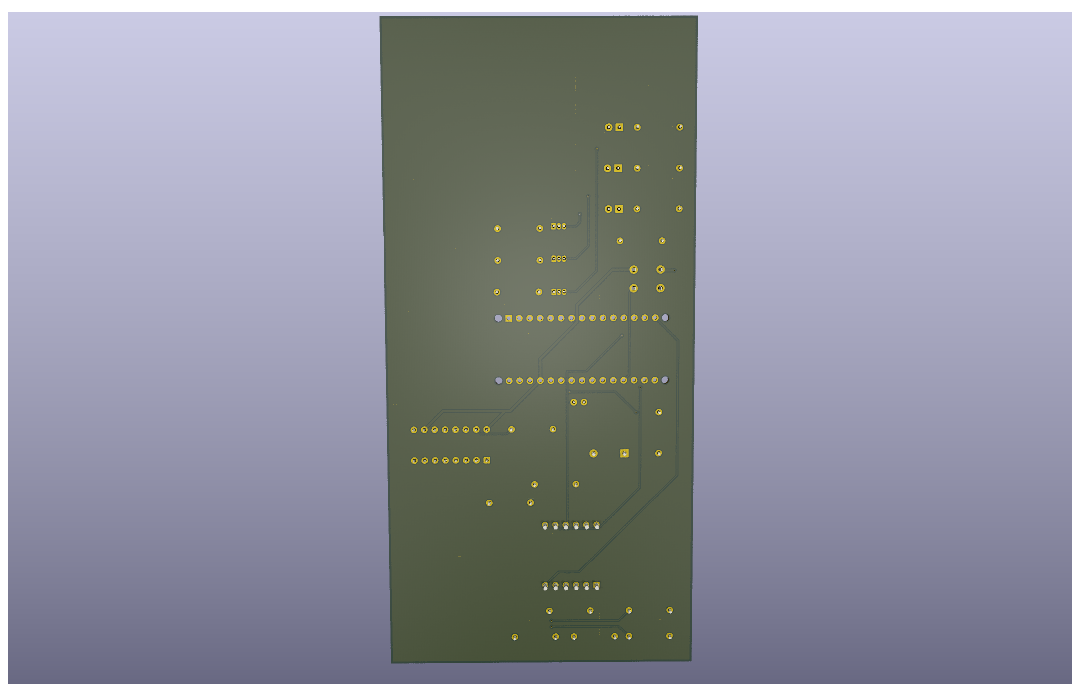
The underside of the PCB design; not a fabricated board.
A little time at the workbench
Explore a simple circuit, then step through one of my PCB designs.
Breadboard learning model
Switch the supply or change the series resistor. A larger resistance lowers the current through the LED.
Idealized DC example: I = (5 V − 2 V) / R. The LED has an assumed 2 V forward drop. Animation shows the current path; it is not a measurement or a wiring guide for my op-amp.
03 / Bill of materials
Component values and references from the repository BOM. Scroll across for the assigned footprints.
| References | Qty | Part / value | Assigned footprint |
|---|---|---|---|
| A1 | 1 | Arduino_Nano_v3.x | Module:Arduino_Nano_WithMountingHoles |
| BZ1 | 1 | Buzzer | Buzzer_Beeper:Buzzer_12x9.5RM7.6 |
| C1 | 1 | 0.1 µF | Capacitor_THT:C_Disc_D5.0mm_W2.5mm_P2.50mm |
| D1,D2,D3 | 3 | LED | LED_THT:LED_D5.0mm |
| Q1,Q2,Q3 | 3 | PN2222A | Package_TO_SOT_THT:TO-92_Inline |
| R1,R3,R5 | 3 | 1000 | Resistor_THT:R_Axial_DIN0207_L6.3mm_D2.5mm_P10.16mm_Horizontal |
| R2,R4,R6 | 3 | 330 | Resistor_THT:R_Axial_DIN0207_L6.3mm_D2.5mm_P10.16mm_Horizontal |
| R10 | 1 | 10k | Resistor_THT:R_Axial_DIN0207_L6.3mm_D2.5mm_P10.16mm_Horizontal |
| R77,RA1,RB1,RC1,RD1,RDPX1,RE1,RF1,RG1 | 9 | 220 | Resistor_THT:R_Axial_DIN0207_L6.3mm_D2.5mm_P10.16mm_Horizontal |
| SW1 | 1 | Pedestrian Button | Button_Switch_THT:SW_PUSH_6mm_H5mm |
| U1 | 1 | 74HC595 | Package_DIP:DIP-16_W7.62mm |
| U2 | 1 | CC56-12SRWA | Display_7Segment:CA56-12SRWA |
Open the working files
Source files and repository notes are preserved as a project record. Notes may describe intended behavior. See the project stages above for what was built and tested.
What stayed with me
Building on a breadboard exposes wiring and integration details that are easy to miss in a diagram.
The prototype and PCB revision need their own clear records.
Keeping editable files and exports together makes it easier to revisit an early design.